A CAT??!! In MY phased array? It's more likely than you think
 This kitty should work
 This kitty was generated @ 14GHz. Way to go kitty!
So as a professional wireless bitch, I do happen to know a thing or two about radio systems, including phased arrays. I just so happen
to know how you can get a phased array to generate a UV plot of a kitty cat :3
I have attempted to put this on real hardware and then measure it in the lab, but measurement requires taking the phase reference from a
particular RFIO, which likely had close to 0 magnitude because I forgot to manually set the gain. Furthermore, the peak gain
might be too low for the test equipment to measure without external amplifiers. Furthermore, I may have ran out of dynamic range for this.
Either way, I WILL try again.
DEMO! In your browser!
I've grabbed the corpse of my chicken scratch code, and dragged it kicking and screaming into the age of webapp (for your enjoyment)
wtf is this shit?
What is a phased array?
 A 2D phased array in the wild
Just a quick primer for those who don't know what they are: phased arrays are arrays of antennas that can be electronically controlled to cause constructive and destructive interference in specific locations in space.
That is to say, you can phase shift each element to get the peaks to line up to electronically steer a beam. Phased array systems are super useful in satellite comms (capacity for multiple beams
to serve multiple users and satellites), radar and DOA/AOA estimation, WiFi kind of, Sonar, and having fun :)
Babby's First Phased Array Model
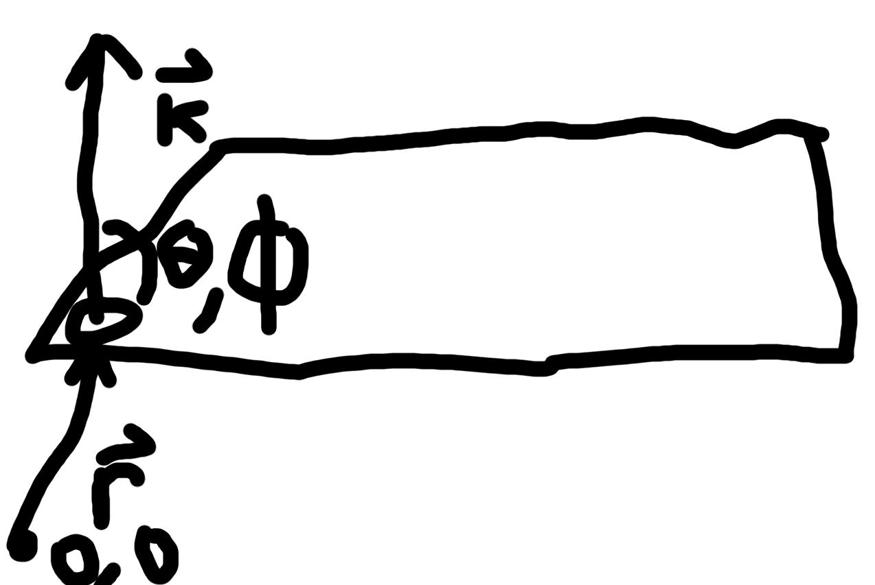 Sorry I will replace this track pad image soon
There are a couple of things to know about any given phased array (well actually there are are a lot). From a theoretical standpoint, it's important to know the element spacing / geometry, the individual antenna element pattern, and the excitation matrix.
Basically, each antenna element can be represented with a vector $\overrightarrow{r} = (\overrightarrow{x},\overrightarrow{y},\overrightarrow{z})$, and the phase of planar propagation in any direction can be represented
by the vector $\overrightarrow{k} = \frac{2\pi}{\lambda}(sin(\theta)cos(\phi), sin(\theta)sin(\phi), cos(\theta))$, where $\phi$ and $\theta$ represent the azimuth and elevation angles (see illustration.)
By taking the dot product $\overrightarrow{r} \cdot \overrightarrow{k}$, you can get a projection of the direction of the wave (sinusoid) onto the element position vector, which provides information on how much
the position of a particular element would change the phase of a wavefront propagating in a particular direction. From this, you can construct the following phasor $e^{\overrightarrow{r}\cdot\overrightarrow{k}}$ which represents that wave.
If you give your antenna element some arbitrary phase and magnitude, represented by $w$, the wave of your element can be represented by $we^{\overrightarrow{r}\cdot\overrightarrow{k}}$. If you want to know how all the elements would affect
a wave propagating in a specific direction, you just sum up all of these wave representations into something called the Array Factor (adjecent to array gain / radiation pattern) with the following equation:
 Example UV plot for different array shapes
 What a beam might look like if you could actually see it
$$AF(\overrightarrow{k}(\theta,\phi)) = \sum_{i=1}^{N} we^{\overrightarrow{r_{i}}\cdot\overrightarrow{k}}$$
And if you for realsies want the Array gain in a specific direction,
$$R(\theta,\phi)AF(\overrightarrow{k}(\theta,\phi))$$
Ok so cool, this basically gives you the radiation pattern at a specific point. You can then run this calculation over a bunch of scan $\theta$s and $\phi$s to get
the total radiation pattern of your antenna. You can then do some math magic to project it into a UV plot.
From babby's first array to arbitrary array synthesis
Ok, so that is all cool and whatnot. But what if you want to make any radiation pattern you want? Well,
you would need to figure out what excitation matrix you need to apply (phase shift and amplitude shift) required to get
the desired pattern.
You can use a method called Woodward Lawson Array synthesis to do this. It's actually not that bad/hard to use.
So this thing:
$$AF=w^{T}\overrightarrow{v}(\overrightarrow{k})$$
Is basically saying that if you multiple some matrix of weights by some steering vector, you get the array factor for that
direction. So like, what if you could theoretically do this for all $\overrightarrow{k}$ for the $\phi$ $theta$ that we care about, and then
just take the inverse to get w. So like:
$$AF[\overrightarrow{v}(\overrightarrow{k})]^{-1}=w^{T}$$
Ok so you can't technically do that because of the different array shapes and whatnot. BUT, if you took a pseudoinverse, you could theoretically
be able to back up an approximate excitation matrix that should be good enough to capture the essence of your target image.
This is basically when the tool does.
I will add the github repo soon, once I scrub some information. Alternatively, just scrape the page if you would like access to the source code.